Arduino: H-Bridge IC
This post will cover how to use an H-Bridge integrated circuit (IC) to reverse the direction of the motors on my robot car. I will also take advantage of the new motor control to improve my obstacle avoidance algorithm. Here is a video showing you what you will have by the end of the tutorial:
Material
For this tutorial, you will need:
- 2WD Robot Car with Ultrasonic Distance Sensor, built in my last posts.
- Texas Instruments L293NE H-Bridge: The Arduino Starter Kit comes with one included.
- Arduino Time Library: Code library.
To understand a little about what an H-Bridge is, I read through this lab.
H-Bridge IC
Because my goal is to reverse the direction of the robot car, I need to reverse the direction of the current in both motors. This can be done by using the L293NE, which has two bridges (the left and right side of the chip). Each pin has a specific funtionality, which is described in this diagram taken from the NYU lab:
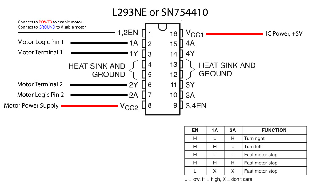
Given this diagram, 6 I/O pins are needed:
- 2 I/O pins for each motors’ enable pin
- 4 I/O pins for each motors’ 2 control pins
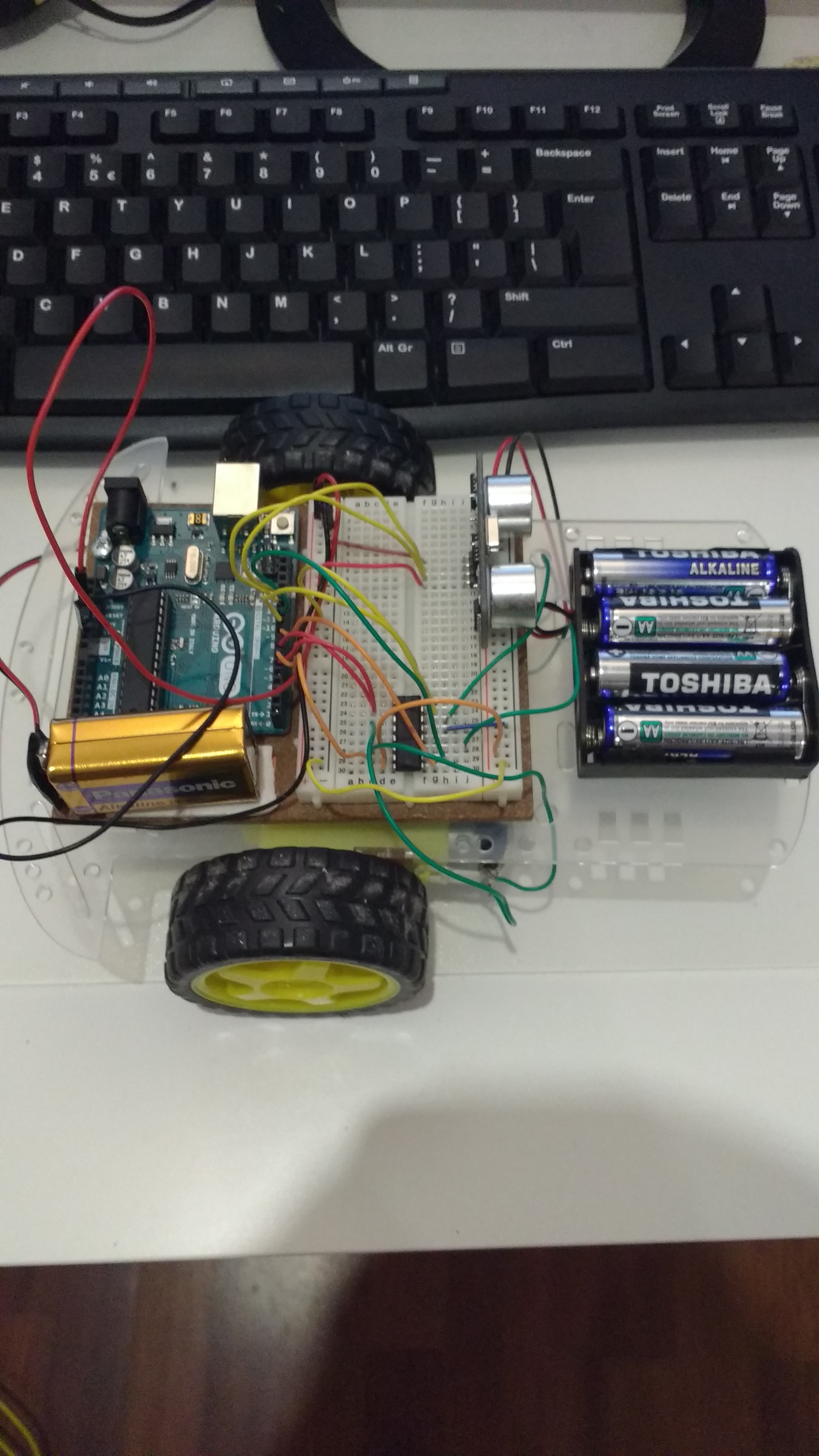
Because I/O pins 11 and 12 are reserved for the ultrasonic distance sensor, I chose I/O pins 5 through 10 to control the motors. Going through the IC’s pins one-by-one, here is how they are connected in my setup:
- Right motor’s enable pin, I/O pin
7. - Right motor’s control pin 1, I/O pin
5. - Right motor’s Terminal 1, hooked up to one side of the right motor.
- Not connected to anything.
- Not connected to anything.
- Right motor’s Terminal 2, hooked up to the other side of the right motor.
- Right motor’s control pin 2, I/O pin
6. - Both motors’ power supply, hooked up to the 9V battery
+column on the breadboard, e.g. not the Arduino’s power supply. - Left motor’s enable pin, I/O pin
8. - Left motors control pin 1, I/O pin
10. - Left motor’s Terminal 1, hooked up to one side of the left motor.
- Not connected to anything.
- Both motors’ ground connection, hooked up to the ground on the 9V battery
-column on the breadboard, e.g. not the Arduino’s ground. - Left motor’s Terminal 2, hooked up to the other side of the right motor.
- Left motor’s control pin 2, I/O pin
9. - IC power, connected to the
+column that connects to the Arduino’s ground.
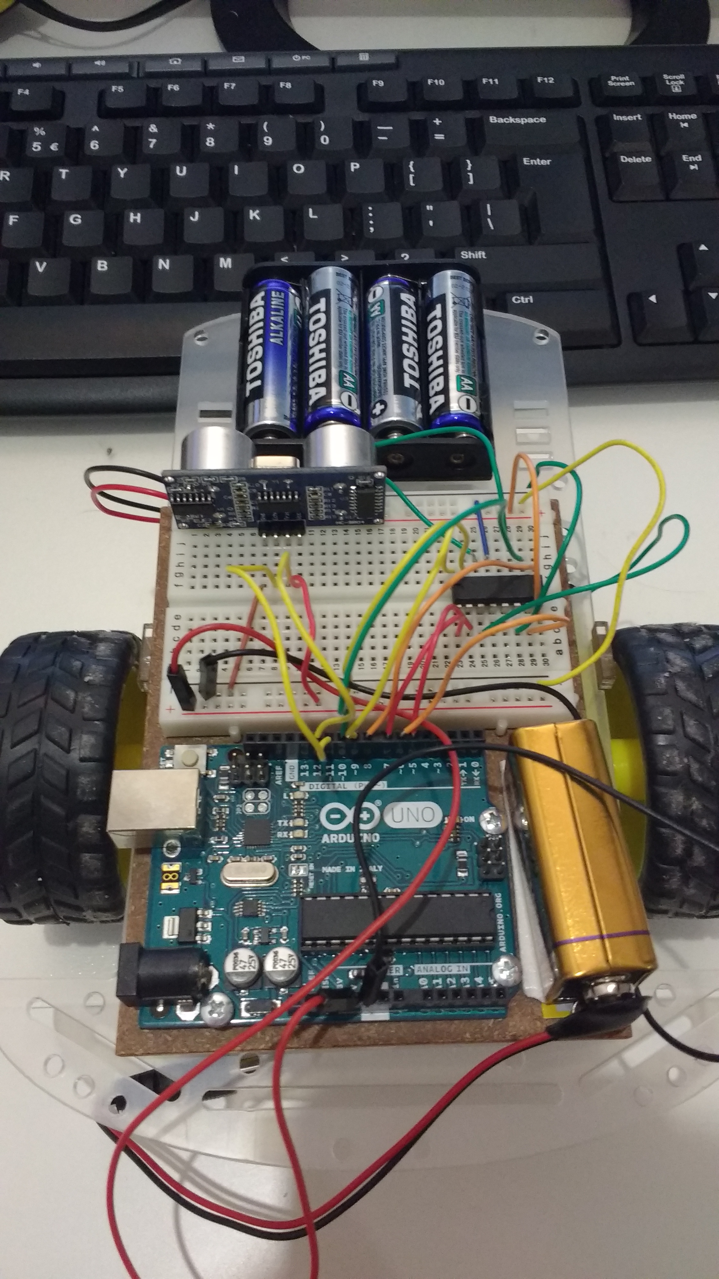
Here are two different views, from the side and from the back, that go with the description above:
Reversing Direction
Supplying voltage to one terminal of a motor will make the motor spin in one direction, while supplying voltage to the other terminal of the motor will make the motor spin in the opposite direction. If both terminals receive voltage, the motor will go forward. Therefore, you must find out which Terminal, when receiving voltage, makes your motor go backwards. After uploading the code below, if one of your motors is running backwards when it should be running forwards (or vice versa), it’s because the terminals were connected differently. If you experience this, just switch the Terminal 1 connection to the Terminal 2 connection and it will be fixed.
To reverse both motors, we must digitalWrite(LOW) to the same Terminal for both motors. In my case, it is Terminal 1 (I/O pins 5 and 9 for the right and left motor respectively) while HIGH and Terminal 2 (I/O pins 6 and 10 for the right and left motor respectively) while LOW that cause both motors to go in reverse. Here is the code to do this:
void reverse() {
  digitalWrite(7, HIGH);  // right motor enable pin
  digitalWrite(8, HIGH);  // left motor enable pin
  digitalWrite(6, LOW);   // right motor Terminal 1
  digitalWrite(5, HIGH);  // right motor Terminal 2
  digitalWrite(10, LOW);  // left motor Terminal 1
  digitalWrite(9, HIGH);  // left motor Terminal 2
}
At any point in time, if the enable pin of a motor is LOW, the motor will turn off, going neither fowards nor backwards. This example stops the car:
void stop() {
  digitalWrite(7, LOW); // right motor enable pin
  digitalWrite(8, LOW); // left motor ennable pin
}
Improved Obstacle-Avoidance Algorithm
Now that I have the ability to reverse the direction of the motors, I can improve upon the obstacle-avoidance algorithm in the last post.
#include <Time.h>
#include <NewPing.h>

// sensor stuff
#define TRIGGER_PIN   12
#define ECHO_PIN      11
#define MAX_DISTANCE  200

// motor stuff
#define E1 7  // enable pin for motor 1
#define E2 8  // enable pin for motor 2
#define I1 6  // control pin 1 for motor 1
#define I2 5  // control pin 2 for motor 1
#define I3 10 // control pin 1 for motor 2
#define I4 9  // control pin 2 for motor 2

NewPing sonar(TRIGGER_PIN, ECHO_PIN, MAX_DISTANCE);

time_t lastStartTime = now();
int distanceToStop = 40;

void setup() {
  pinMode(E1, OUTPUT);
  pinMode(E2, OUTPUT);

  pinMode(I1, OUTPUT);
  pinMode(I2, OUTPUT);
  pinMode(I3, OUTPUT);
  pinMode(I4, OUTPUT);

  Serial.begin(115200);
}

void loop() {
  unsigned int uS = sonar.ping(); // send ping and gets time in milliseconsds (uS)
  unsigned int distance = uS / US_ROUNDTRIP_CM;
  Serial.print("Ping: ");
  Serial.print(distance); // Convert ping time to distance and print result (0 = outside set distance range, no ping echo)
  Serial.println("cm");

  unsigned int diffSinceLastStart = second(lastStartTime);
  // set the distance to stop based upon time since last started
  Serial.println("DiffSinceLastStart : " + diffSinceLastStart);
  if (diffSinceLastStart < 1) {
    distanceToStop = 15;
  } else if (diffSinceLastStart < 2) {
    distanceToStop = 25;
  } else if (diffSinceLastStart < 3) {
    distanceToStop = 40;
  } else {
    distanceToStop = 50;
  }
  Serial.println("Distance to stop : " + distanceToStop);

  if (distance > distanceToStop || distance == 0) {
    // record this as last start time
    lastStartTime = now();

    // enable both motors
    digitalWrite(E1, HIGH);
    digitalWrite(E2, HIGH);
    digitalWrite(I1, HIGH);
    digitalWrite(I2, LOW);
    digitalWrite(I3, HIGH);
    digitalWrite(I4, LOW);

    // delay 50 ms for the next ping
    delay(50);
  } else {
    // stop
    digitalWrite(E1, LOW);
    digitalWrite(E2, LOW);
    delay(200);

    // back up a little
    digitalWrite(E1, HIGH);
    digitalWrite(E2, HIGH);
    digitalWrite(I1, LOW);
    digitalWrite(I2, HIGH);
    digitalWrite(I3, LOW);
    digitalWrite(I4, HIGH);

    delay(250);
    digitalWrite(E1, LOW);
    digitalWrite(E2, LOW);
    delay(200);

    unsigned int randomDirection = random(0,2);
    if (randomDirection == 0) {
      // run left motor for a second
      digitalWrite(E1, HIGH);
      digitalWrite(I1, HIGH);
      digitalWrite(I2, LOW);
    } else {
      // run right motor for a second
      digitalWrite(E2, HIGH);
      digitalWrite(I3, HIGH);
      digitalWrite(I4, LOW);
    }
   delay(300);
  }
}
Conclusion
After uploading the code to the robot, or watching the video above, we can see that it is definitely an improvement on the last algorithm we had. The ability to back up really gives some breathing room to the car in order for it to find empty space more easily. However, the random direction can cause problems if it is close to a corner. To solve this issue, I am going to mount the ultrasonic distance sensor on a Servo motor, allowing the car to look left and right in order to make a decision on which way to turn.