Arduino: Building a Robot Car
This post is the first in a series about my Arduino project, which is building a robot car that uses a ultrasonic sensor to detect and avoid obstacles. Many examples that I have found on Instructables or across the internet make use of a “Motor Shield.”
However, I am currently making use of my Arduino Starter Kit, and therefore do not have a motor shield. Although the motor shield can more efficiently control the motor, while reading through the Arduino Starter Kit projects book, I realized that it is possible to create the car using transistors that come with the kit, saving $15 on the motor shield and learning a little bit more about circuits. Throughout my tutorials, keep in mind that I am learning circuits myself, so I am not going to be explaining exactly what’s going on, just the changes that I have made to the basic circuit to achieve my goal.
Materials
This is the list of things that I have purchased and have ready for this project:
-
Arduino Start Kit : I live in Europe, so I have the “Genuino.”
-
2WD Motor Robot Car Chassis Kit : Anything with two motors and wheels should work.
-
Battery Clip Connector : to connect a 9v battery to your Arduino (instead of USB for example).
Starting the project
Here is a quick video showing what you should have by the end of this post. It will be a unconstructed version of the basic setup of the motors. My next posts will continue to elaborate on this base, using the ultrasonic sensor and anything else that I indroduce as my project goes on.
I decided to start this project after completing the Starter Kit’s tutorial 09 “Motorized Pinwheel.” Here is the tutorial’s circuit:
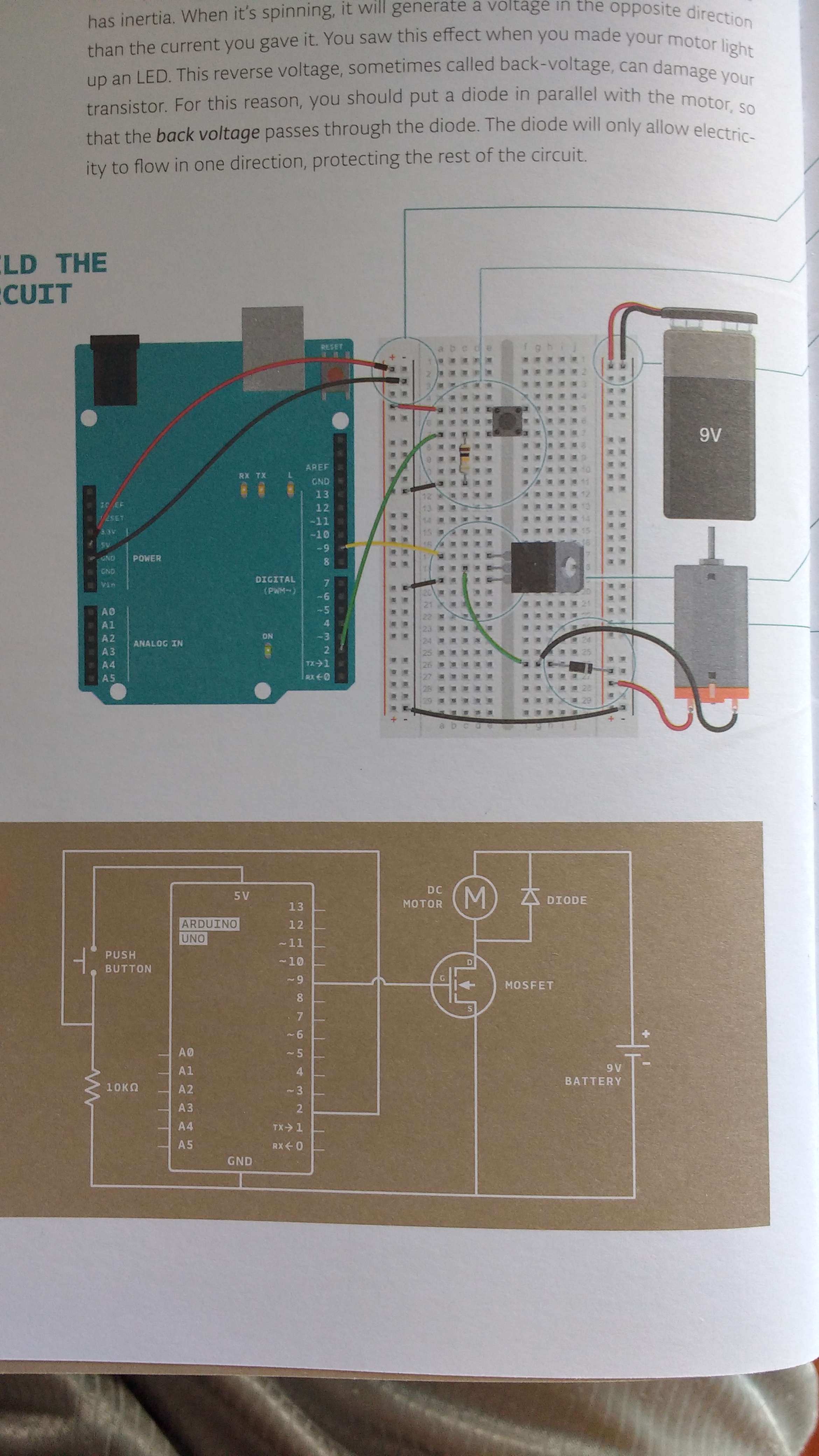
The Circuit
Building the circuit for this tutorial, I wondered if it was possible to add another transistor next to the current transisor in the breadboard column e. Making the assumption that I will simply have another motor, I added another transistor to the breadboard connected to another Digital Input/Output. Then I connected the transistor to the right side of the breadboard (that contains the motor and its battery) making sure to add another diode so that the voltage can only go one way, into my motor and not back into my circuit. Here is what I came up with:
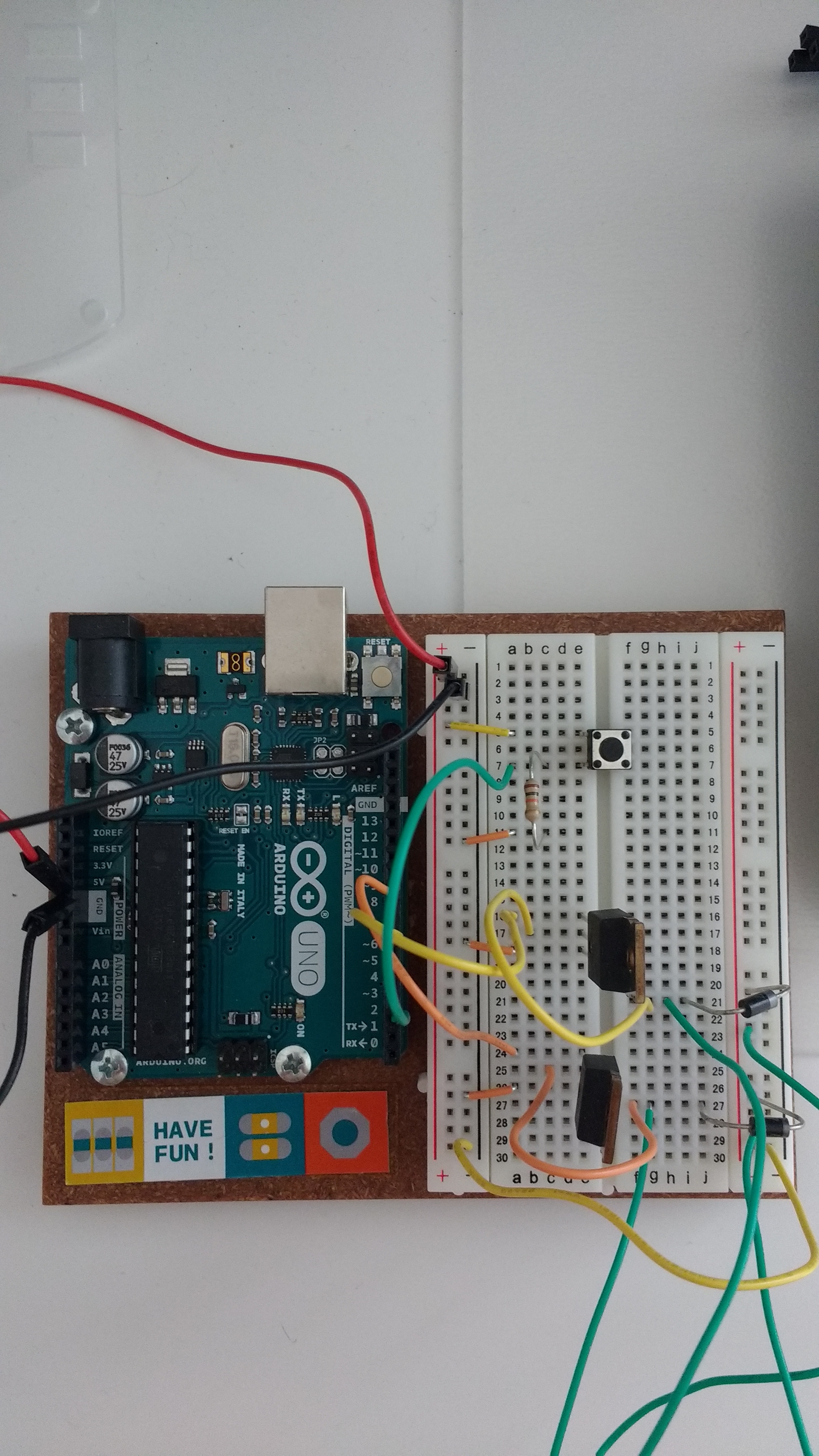
Here’s another view:
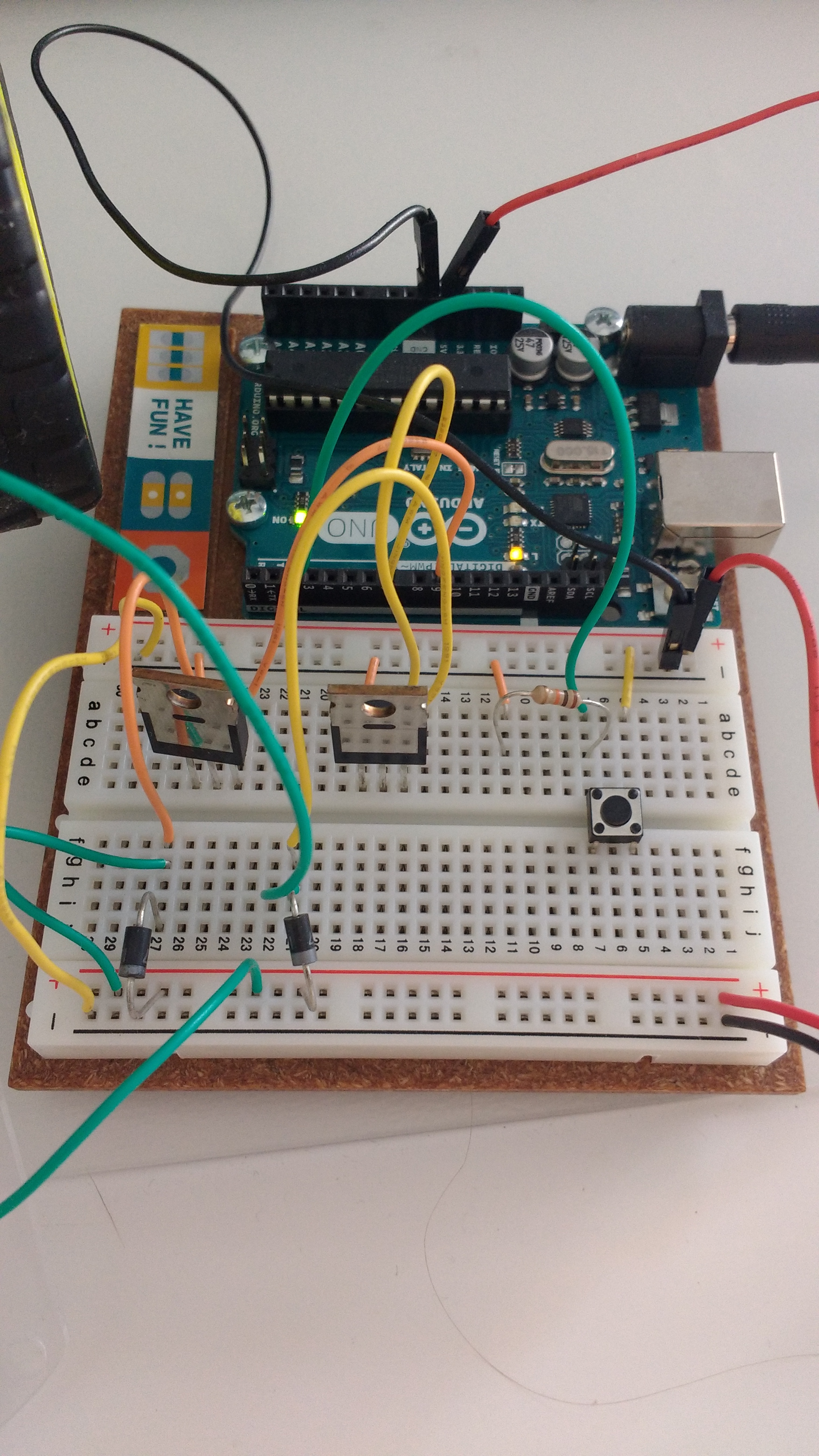
Make sure that you hook the transistor gates (the left-most pins of each transitor, which are rows 16 and 24) to Digital Inputs/Outputs ~9 and 7 respectively for the circuit to work with my code. If you are writing your own code, just make sure to remember which Digital Inputs/Outputs you are using and hook up the gates to any input you want.
The transistors’ middle pins (the drain, or rows 17 and 25) are connected to the ground of the motor. Notice how row 17 of the left side of the breadboard becomes row 21 for example. Then, connect the ground to the power supply with a diode, making sure that the cathode (negative end with the grey bar) is connected to the motor’s power supply and the anode (positive end) is connected to the ground of the power supply. This prevents voltage from going back into your circuit.
The transistors’ right pins (the source) are connected to the ground of the circuit (column - of the left side of the breadboard).
Note that there is a momentary switch on rows 5 through 7. This is simply there to test that the motors are working properly. I will be removing it in the next post.
Code
Here is the code that you will need to upload to your Arduino. Remember that this assumes your motors are connected to Digital 7 and 9. I have left some code for debugging in case you are having a little trouble:
const int switchPin = 2;
const int leftMotor = 9;
const int rightMotor = 7;
int switchState = 0;

// sets which pins are our motors
void setup() {
  pinMode(leftMotor, OUTPUT);
  pinMode(rightMotor, OUTPUT);
  pinMode(switchPin, INPUT);
  Serial.begin(9600); // for debugging
}

void loop() {
  switchState = digitalRead(switchPin);

  // if the switch pin is pushed
  if (switchState == HIGH) {
    Serial.println("high");

    // supply power to motors
    digitalWrite(leftMotor, HIGH);
    digitalWrite(rightMotor, HIGH);
  } else { // the switch pin is not pushed
    Serial.println("low");

    // do not supply power to motors
    digitalWrite(leftMotor, LOW);
    digitalWrite(rightMotor, LOW);
  }
}
Connecting Everything
Once you have the code uploaded to your Arduino, replace the USB cable with a 9v battery with the battery clip mentioned above in the Materials section. Build your 2WD Chassis set and make sure your motors are going in the right direction. You can do this by connecting the AA battery pack to the motors and see which way the wheels turn. Connect the AA battery pack to the breadboard’s right side ground and power, and then connect the ground and power of the circuit to the motors (one power and one ground to each motor). Your setup should look like this:
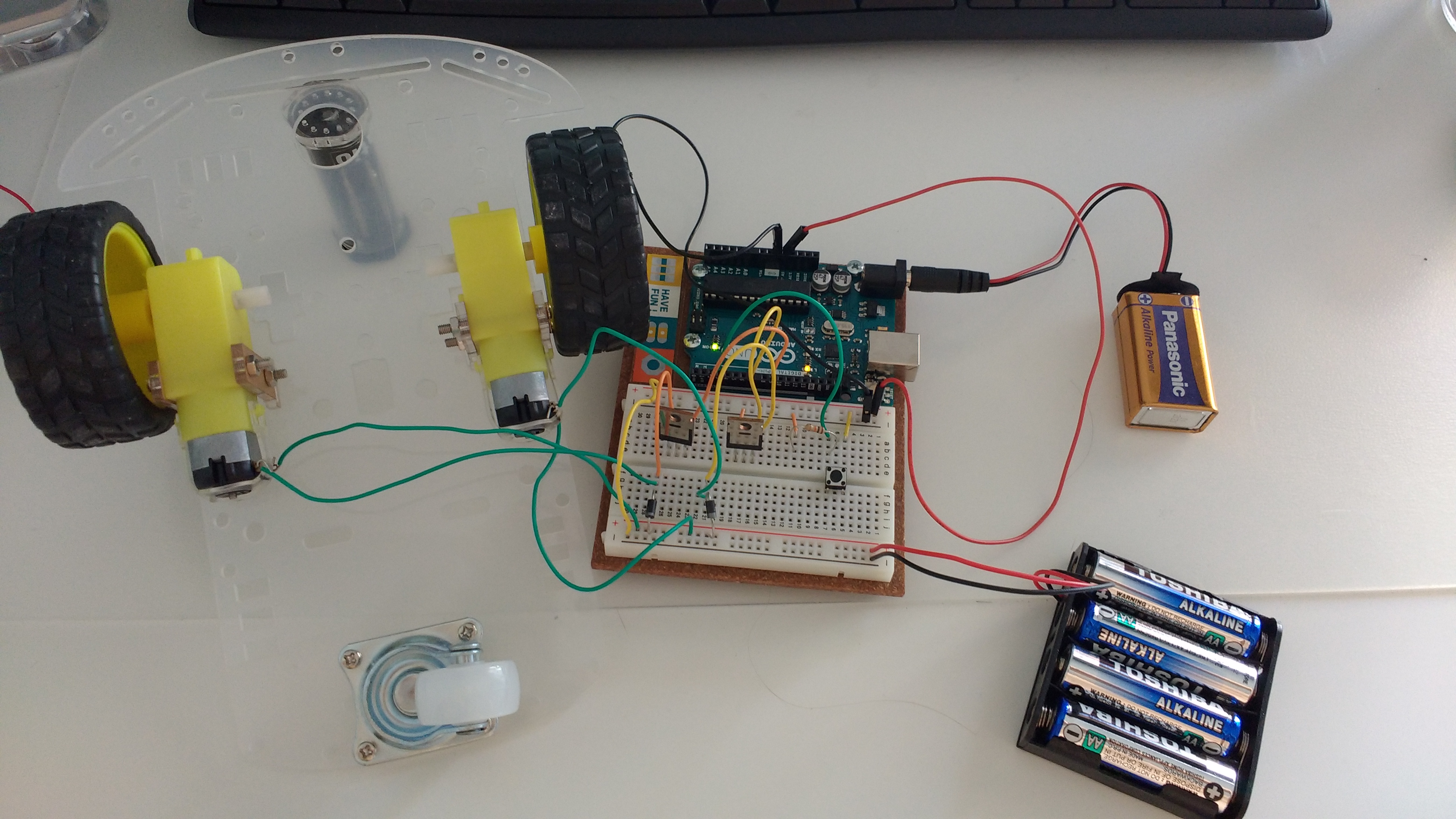
Conclusion
Clicking with your finger on the switch pin should make the wheels turn! Taking your finger off should make them stop. If this is not happening, open your Serial console in your Arduino IDE and debug using the statements that I have added or any other needed statements. In the next post, I will be reordering the breadboard a little to fit the ultrasonic distance sensor, removing the switch pin, and writing the code for the sensor.